Split hand-wired ergonomic keyboard with QMK
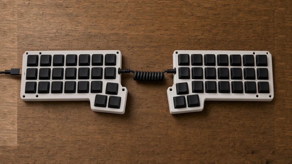
A 42-key split keyboard (two halves of 3x6 keys plus 3 thumb keys) that you hand-wire with diodes in a printed case, controlled by two Adafruit KB2040 boards running QMK and joined by a TRRS cable.
Safety first
- Never plug or unplug the TRRS cable while USB is connected; it can short power to a data pin and damage a controller.
- Solder in a ventilated area and wash your hands after handling leaded solder.
Parts
| Part | Qty | Approx. each | Subtotal |
|---|---|---|---|
| Adafruit KB2040 RP2040 keyboard controllerPrice seen $9.95 each on Adafruit (Nov 12, 2026). Pro Micro footprint, USB-C, RP2040.Adafruit | 2 | $9.95 | $19.90 |
| Gateron Milky Yellow Pro switches (pack of 45)42 needed. MX-style, 3-pin. Typical $12-22, no verified link.Amazon (search) | 1 | $15 | $15 |
| XDA blank PBT keycap setBlank keycaps avoid layout mismatches on a split board. Typical $18-35, no verified link.Amazon (search) | 1 | $25 | $25 |
| 1N4148 diodes (100-pack)Typical $4-8, no verified link.Amazon (search) | 1 | $6 | $6 |
| PJ-320A TRRS jack (10-pack)Typical $4-8, no verified link.Amazon (search) | 1 | $6 | $6 |
| 3.5 mm TRRS cable, 4-pole, 1 mTypical $6-12, no verified link.Amazon (search) | 1 | $8 | $8 |
| 22 AWG solid-core hookup wire kitTypical $12-20, no verified link.Amazon (search) | 1 | $15 | $15 |
| M2 screw assortmentTypical $6-11, no verified link.Amazon (search) | 1 | $8 | $8 |
| Estimated total (parts only) | $102.90 | ||
Typical US prices, checked 2026-11-12. Prices change and multi-packs are often cheaper per piece.
As an Amazon Associate I earn from qualifying purchases. Prices change; check the store.
Filament
PLA (1.75 mm): about 300 g (100.7 m), roughly 16 h of printing.
PLA, 0.2 mm layers, 30% infill, 4 walls for the switch plates so switches clip in firmly. Check that MX switch holes are 14.0 mm.
AI agents you'll use
- Code helper (ChatGPT, Claude, Gemini or Grok): Writes the QMK keyboard definition (keyboard.json) for a hand-wired split with your row and column pins, and helps you build and flash it.
- Layout helper: Designs a 42-key layout with layers for numbers, symbols and navigation based on what you type most.
Tools
- Soldering iron with a fine tip
- Flush cutters
- Wire stripper
- Multimeter with continuity beep
- Tweezers
- USB-C data cable
What you'll learn
- How a keyboard matrix and diodes work
- Hand-wiring rows and columns
- Building and flashing QMK firmware
- Designing a layout with layers
Build the keyboard you will use every day. A split 42-key board keeps your hands shoulder-width apart, and hand-wiring it teaches you exactly how every key press reaches the computer.
What you'll build
Two mirror-image halves, each with 21 keys (three rows of six plus three thumb keys) in a printed plate and case. Each half is a 4-row x 6-column matrix with a 1N4148 diode per switch and its own KB2040. The halves talk over a TRRS cable using QMK's split serial driver; you plug USB into either side.
The cost range is $90-115 for the parts listed below, allowing about 10% either way for price swings.
Print the parts
Search Printables for a hand-wire 3x6+3 split plate and case (Corne-style layouts are common), check the license and credit the designer. Print one plate first and test that switches click in firmly.
Wiring
Per half: diodes from each switch to its row wire (black band toward the row), switch other pin to the column wire. Rows and columns go to KB2040 GPIO pins you list in QMK.
| From | To | Notes |
|---|---|---|
| Row wires (4: three key rows plus the thumb row) | 4 KB2040 GPIOs | Through the diodes, band toward the row (COL2ROW). |
| Column wires (6) | 6 KB2040 GPIOs | |
| TRRS jack: tip / ring 1 / ring 2 / sleeve | 5V(VBUS) / data GPIO / unused / GND | Use the same data pin on both halves for single-wire serial; check the QMK split docs for RP2040. |
| USB-C | Either half | The half with USB is the master by default. |
Step-by-step
- Print and test-fit the plates; clip in all switches.
- Bend each diode leg into a row wire and solder; check every diode direction.
- Strip short windows in solid wire for the columns and solder them on.
- Beep every switch with the multimeter from its row to its column.
- Wire rows, columns and the TRRS jack to each KB2040.
- Generate a QMK keyboard definition with the helper and build firmware for the RP2040.
- Flash each half (hold BOOT, drag the .uf2 file).
- Test every key with a key-tester page, then tune the layout and layers.
Code
QMK firmware built with the QMK CLI; the keyboard is defined in keyboard.json plus a keymap.
Prompt for the code helper:
Create a QMK keyboard definition for a hand-wired split keyboard on two Adafruit KB2040 (RP2040) boards.
Each half: 4 rows (GP pins <list>) x 6 columns (GP pins <list>), diodes COL2ROW, 21 keys: three rows of 6 and a thumb row of 3 on columns 3-5. Split over a TRRS single-wire serial link on GP1.
Use current QMK keyboard.json format and RP2040 split settings from docs.qmk.fm, and give me a 3-layer keymap.
Troubleshooting
- A whole row or column is dead: A broken solder joint or wrong pin in the config. Beep it out.
- One key types two characters: Missing or reversed diode on that key.
- Right half does nothing: TRRS data pin mismatch, or the split driver not enabled. Plug the cable in before USB.
Files, code and docs
- QMK firmware (GPL-2.0)
- QMK hand-wiring guide (Vendor docs)
- QMK split keyboard docs (Vendor docs)
- Corne keyboard (foostan/crkbd, layout reference) (CC-BY-4.0)
Last checked 2026-11-12. Double-check parts against your own board and seller listings before you buy.