Self-balancing two-wheel robot
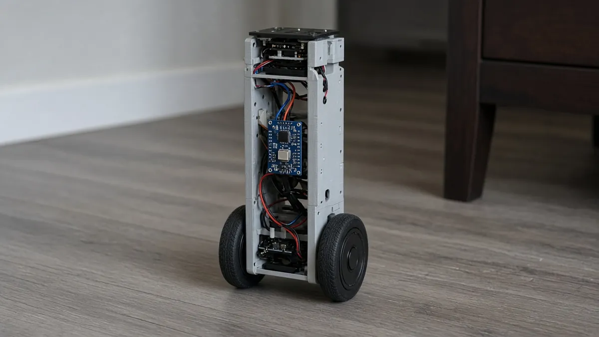
A narrow two-wheel robot that uses an MPU6050 inertial sensor and a fast control loop to stay upright. Most of the work is mechanical alignment and patient PID tuning, with an AI helper reading your logs.
Safety first
- Use the correct charger for your pack. Charge LiPo in a fire-safe bag and never unattended. Stop if a pack swells or gets hot.
- The robot can lurch off a desk or pinch a finger in a wheel. Tune it on a tether or in a foam cradle, then move to the floor.
- Unplug power before you change wiring. Keep motor voltage off the ESP32 3.3 V pin.
- This is a low-voltage project. No mains wiring.
Parts
| Part | Qty | Approx. each | Subtotal |
|---|---|---|---|
| Espressif ESP32-DevKitC-32E (DevKitC V4) development boardOfficial Espressif 38-pin DevKitC V4 with ESP32-WROOM-32E (4 MB). Micro-USB port, not USB-C. Buy only the official 38-pin Micro-USB board, not a USB-C or 30-pin clone. Primary listing: Mouser 356-ESP32-DEVKITC32E, $10.20, 1,701 in stock on Nov 12, 2026, per Findchips (https://www.findchips.com/search/ESP32-DEVKITC-32E). The Mouser US page itself returned 403 to a direct fetch, so click-confirm the US storefront before you order. Mouser Netherlands listed 1,622 in stock at €8.60 the same day. Do not use DigiKey as the default today (search snippets showed 0 in stock / long lead time). Official Amazon listing https://www.amazon.com/dp/B09MQJWQN2 was still unavailable; use it if it returns. Amazon search for the official board: https://www.amazon.com/s?k=ESP32-DevKitC-32E. Adafruit #3269 remains $15.00 and was out of stock (https://www.adafruit.com/product/3269). Typical $10-16.Mouser · price seen on 2026-11-12 | 1 | $10.20 | $10.20 |
| HiLetgo GY-521 MPU-6050 6-DoF module (3-pack)A 3-pack is typical; one module is enough. Official Adafruit 3886 is a pricier alternative. Typical $2.5-$4.5 each (or see pack note). ASIN confirmed. Typical $8-12 for the 3-pack; unit price is an estimate. Adafruit's official MPU-6050 (product 3886) was $12.95 on Adafruit the same day.Amazon | 1 | $3.50 | $3.50 |
| SparkFun Motor Driver - Dual TB6612FNG (with headers)Price seen ~$14.50 on SparkFun, Nov 12, 2026. Price seen $14.50 on SparkFun. Amazon listings exist but had few reviews and a higher price, so the official page is the source.SparkFun · price seen on 2026-11-12 | 1 | $14.50 | $14.50 |
| N20 geared DC motor with Hall encoder and wheel (pair typical)Typical $6-12 each, no verified link. Match the motor to the chassis.Amazon (search) | 2 | $8 | $16 |
| 2S Li-ion or LiPo pack plus a compatible chargerTypical $12-25, no verified link. Use a fire-safe bag for LiPo.Amazon (search) | 1 | $18 | $18 |
| M3 screws, standoffs, and jumper wiresTypical $4-8 for a small hardware kit, no verified link.Amazon (search) | 1 | $5 | $5 |
| Estimated total (parts only) | $67.20 | ||
Typical US prices, checked 2026-11-12. Prices change and multi-packs are often cheaper per piece.
As an Amazon Associate I earn from qualifying purchases. Prices change; check the store.
Filament
PLA (1.75 mm): about 100 g (33.6 m), roughly 7 h of printing.
PLA or PETG, 0.4 mm nozzle, 0.2 mm layers, 30% infill for a stiff chassis (flex makes tuning miserable), 3-4 walls, supports only where motor pockets need them.
AI agents you'll use
- Code helper (ChatGPT, Claude, Gemini or Grok): Writes the IMU read, complementary filter and a timed PID loop, with gains as clearly labeled constants - not a claimed universal tune.
- Tuning helper: Reads a short log of angle, rate and motor output and suggests whether to change P, D, loop rate or the balance-angle offset first.
- Mechanical check helper: Reviews IMU placement, wheel concentricity and whether the chassis is stiff enough to be worth tuning.
Tools
- 3D printer
- Calipers
- Small screwdriver
- Multimeter
- Computer with Arduino IDE or PlatformIO and a serial plotter
- USB data cable
- Foam cradle or a loose safety tether
What you'll learn
- Reading a MPU6050 gyroscope and accelerometer
- Combining them with a complementary filter
- Why a PID loop is sensitive to mass, loop rate and motor deadband
- Using motor encoders if your motors include them
A two-wheel balancer is an inverted pendulum: if the control loop is late, or the chassis flexes, or the IMU is floppy, it falls. Treat the first afternoon as a sensor and wiring job, and only then start tuning. Do not paste someone else's PID numbers and expect them to work on your motors.
What you'll build
A stiff, narrow printed chassis with two wheels on one axis, an MPU6050 bolted down firmly, a TB6612FNG driver, and an ESP32 running a 100-200 Hz control loop if the board can sustain it. Encoders are optional but they make position hold much easier later.
Print the parts
A candidate chassis is Chahatesh's "ESP32 PID self-balancing robot" on Printables (model 1767117). The license is CC BY-NC 4.0 (designer GitHub README and a SliSearch Printables scrape dated Sept 3, 2026) — re-check the live Printables badge before you print, credit the designer, and do not host or redistribute the files. Confirm it uses N20 motors with encoders (not TT motors) before you adopt it, or pick another open-licensed MPU-6050 chassis that matches the motors in the parts list. A rigid, narrow frame with the mass stacked above the axle works better than a floppy kit.
Print with the settings above. Mount the motors so both wheels share one axis and spin freely. Leave a solid pad for the IMU, close to the wheel axis or in a documented position you then keep consistent.
Wiring
| From | To (ESP32, unless noted) |
|---|---|
| MPU6050 VCC | 3.3 V, unless your module is clearly marked for 5 V with its own regulator |
| MPU6050 SDA, SCL | GPIO 21, GPIO 22 |
| MPU6050 GND | Common ground |
| TB6612 PWMA, PWMB | GPIO 25, GPIO 14 |
| TB6612 AIN1, AIN2 | GPIO 26, GPIO 27 |
| TB6612 BIN1, BIN2 | GPIO 32, GPIO 13 |
| TB6612 STBY | GPIO 33 |
| TB6612 VM | Battery, within the driver limits |
| Optional left encoder A, B | Two interrupt-capable GPIOs, for example 16 and 17, only if you have encoders |
A flapping IMU breakout looks like noise. Bolt it down and keep the I2C wires short.
Step-by-step
- Print and assemble the chassis. Confirm both wheels are concentric and free-spinning.
- Bolt the MPU6050 down square to the chassis and wire I2C.
- Install the Arduino IDE, the ESP32 core, and the Adafruit MPU6050 library (or I2Cdevlib if you prefer).
- Hang the robot in a foam cradle or from a loose tether. Flash an IMU-only sketch and plot the angle while you tilt it by hand. Fix the axis mapping before you touch motors.
- Wire the driver and confirm both wheels drive "forward" in the same direction.
- Ask the code helper for a complementary filter plus a PID loop, with P, I, D and a balance-angle offset as labeled constants.
- Start with only P, a small value, still on the tether. Increase P until it holds briefly, add D to damp oscillation, then a little I if it drifts.
- When it balances on the tether, try the floor. Log angle, rate and motor output whenever it falls, and give that log to the tuning helper instead of twisting all three gains at once.
- If you have encoders, add a slower outer loop later for position hold.
Code
Prompt for the code helper:
Write an Arduino-ESP32 sketch that reads an MPU6050 (SDA 21, SCL 22) using the Adafruit MPU6050 library, applies a complementary filter to estimate tilt, and runs a PID loop on two DC motors through a TB6612FNG (PWMA 25, AIN1 26, AIN2 27, PWMB 14, BIN1 32, BIN2 13, STBY 33).
Leave PID gains and the balance-angle offset as clearly labeled constants. Do not invent a "universal" gain set. Use a timed loop, print angle and motor output, and comment the axis mapping so I can change it after I mount the board.
First get a stable angle at rest:
#include <Adafruit_MPU6050.h>
#include <Adafruit_Sensor.h>
Adafruit_MPU6050 mpu;
void setup() {
  Serial.begin(115200);
  if (!mpu.begin()) { while (1) delay(10); }
}
void loop() {
  sensors_event_t a, g, temp;
  mpu.getEvent(&a, &g, &temp);
  // Confirm this axis mapping after you mount the board; do not assume it.
  float angleAcc = atan2(a.acceleration.z, a.acceleration.x) * 180.0 / PI;
  Serial.println(angleAcc);
  delay(10);
}
Troubleshooting
- Angle jumps around at rest: the IMU is loose, the wiring is long, or you need a lower gyro/accelerometer range and a little filtering.
- It oscillates twice a second and falls: usually too much P or too little D, or a flexible chassis. Lower P first.
- It always falls one way: the balance offset is wrong, or one motor is weaker or reversed.
- Motors fight the fall too late: the loop is too slow (
delay()in the loop is a common cause) or the driver STBY pin is not held high. - Board will not boot or flash after rewiring: avoid GPIO 12 for motor pins. It is a strapping pin (flash-voltage select), which is why BIN1 uses GPIO 32 here.
Print files
- ESP32 PID self-balancing robot (Chahatesh, CC BY-NC 4.0. We don't host this file.)
Files, code and docs
- Adafruit MPU6050 library (BSD-3-Clause)
- Jeff Rowberg I2Cdevlib MPU6050 (MIT)
- ESP32 PID self-balancing robot (Chahatesh, Printables 1767117) (CC BY-NC 4.0 — link only, do not host or redistribute (designer GitHub README and a SliSearch Printables scrape dated Sept 3, 2026; re-check the live Printables badge))
- Installing the Arduino-ESP32 core (Espressif docs) (Vendor docs)
Last checked 2026-11-12. Double-check parts against your own board and seller listings before you buy.